
Steel tanks for flammable and combustible liquids
Run consultation | Check Fact Cross References | Check Fact Translations
// Codebase: Steel tanks for flammable and combustible liquids (AS 1692)
// Author/Contributor: Andrew Davies and Andrew Mowbray
// Created: 6 April 2023
// Last Updated: 6 April 2023
//
//
// AS 1692 Steel tanks for flammable and combustible liquids
//
// Designation: AS 1692-2006
// Committee: ME-017, Flammable and Combustible Liquids
// Project ID: 5874
// Project Manager: Dawn Lindsay
// Stage: Pre-Publication
//
// © Standards Australia Limited
//
// All rights are reserved. No part of this work may be reproduced or copied
// in any form or by any means, electronic or mechanical, including
// photocopying, without the written permission of the publisher, unless
// otherwise permitted under the Copyright Act 1968
//
CONTEXT AS 1692-2006
THING the tank
NUMBER the height of the tank UNIT metres
GOAL RULE Preface PROVIDES
ASSERT This Standard was prepared by Standards Australia Committee ME-017,
Flammable and Combustible Liquids to supersede AS 1692—1989. AND
This new edition has been revised to include new standards and designs to
which tanks may be constructed and tested. References to ‘approvals’ by
authorities have been removed, in line with current regulatory practices. AND
This Standard incorporates Amendment No. 1 (August 2006). The changes required
by the Amendment are indicated in the text by a marginal bar and amendment
number against the clause, note, table, figure or part thereof affected. AND
The objective of this Standard is to provide requirements and recommendations
for the design and construction of a range of types of steel tanks suitable
for the storage of flammable and combustible liquids. AND
This Standard is limited to tanks made of steel and stainless steel, and
includes tanks with integral secondary containment. AND
Thicknesses of materials are based on empirical data, being the result of
experience rather than stress calculations, the exception being tanks of
Category 6 (e.g. those built to API 650). AND
The term ‘normative’ has been used in this Standard to define the application
of the appendix to which it applies. AND
A ‘normative’ appendix is an integral part of the Standard.
GOAL RULE Clause 1.1 Scope PROVIDES
the tank is within the scope of this Standard ONLY IF
there is an issue in relation to the design of the tank AND/OR
there is an issue in relation to the construction of the tank AND
the tank is a steel tank within the meaning of the Standard AND
the tank is for the storage of flammable and combustible liquids AND
the tank is used to store substances that are liquid at normal temperatures
and pressures AND
the shell thicknesses of the tank specified in this Standard are within
assumptions
IF the tank is within the scope of this Standard THEN
this Standard sets out requirements for tank joints and accessories
(e.g. vents, manholes, fill level indicators) and specifies tank testing
requirements AND
this Standard does not insist on compliance with any particular
material Standards, or the use of specific grades of materials
RULE Clause 1.1 Shell Thickness PROVIDES
the shell thicknesses of the tank specified in this Standard are within
assumptions ONLY IF
clause 1.1 (a) applies AND
clause 1.1 (b) applies AND
clause 1.1 (c) applies AND
clause 1.1 (d) applies AND
clause 1.1 (e) applies AND
clause 1.1 (f) applies AND
clause 1.1 (g) applies AND
clause 1.1 (h) applies AND
clause 1.1 (i) applies OR
there is adequate compensation for use of thinner materials
RULE Clause 1.1 (a) PROVIDES
clause 1.1 (a) applies ONLY IF
stresses on the tank will be comparatively low
RULE Clause 1.1 (b) PROVIDES
clause 1.1 (b) applies ONLY IF
the liquid being stored is no more corrosive than normal petroleum products
RULE Clause 1.1 (c) PROVIDES
clause 1.1 (c) applies ONLY IF
the density of the liquid being stored is not greater than 1000 kg/m3
RULE Clause 1.1 (d) PROVIDES
Clause 1.1 (d) applies ONLY IF
the tank needs to be reasonably sturdy for handling and any transport
RULE Clause 1.1 (e) PROVIDES
clause 1.1 (e) applies ONLY IF
an allowance for corrosion needs to be made
RULE Clause 1.1 (f) PROVIDES
clause 1.1 (f) applies ONLY IF
liquid levels after normal filling will not be substantially above the
‘tank full’ level
RULE Clause 1.1 (g) PROVIDES
clause 1.1 (g) applies ONLY IF
no allowance is made for the effect of filling an extended pipe to a
level that is substantially above that of the tank
RULE Clause 1.1 (h) PROVIDES
clause 1.1 (h) applies ONLY IF
the pressure in the vapour space will not exceed 35 kPa
RULE Clause 1.1 (i) PROVIDES
clause 1.1 (i) applies ONLY IF
the length-to-diameter ratio of an above-ground tank on two supports
does not exceed 5
RULE Clause 1.1 (j) PROVIDES
clause 1.1 (i) applies ONLY IF
the tank shell is not stiffened
RULE Clause 1.1 (k) PROVIDES
clause 1.1 (k) applies ONLY IF
the tank is constructed of commercial grade low carbon steel
RULE Clause 1.1 thinner materials PROVIDES
there is adequate compensation for use of thinner materials ONLY IF
there is suitable compensation by shaping, corrugating, bracing or
stiffening the tank AND
the design~demonstrates mechanical properties that are at least
equivalent to a similar size of tank built to this Standard
ASSERT there is greater scope for use of thinner materials in the case
of stainless steel tanks
GOAL RULE Clause 1.2 Application PROVIDES
this Standard is applicable ONLY IF
the tank is within the scope of this Standard AND
the tank is constructed of commercial grade low carbon steel AND/OR
the tank is constructed of stainless steel AND
BEGIN
the tank is for the storage of flammable and combustible liquids OR
BEGIN
the tank has integral secondary containment such as those approved
by Underwriters Laboratories (UL) AND
the tank has fire-rated secondary containment
END
END AND
clause 1.2(a) does not apply AND
clause 1.2(b) does not apply AND
clause 1.2(c) does not apply
RULE Clause 1.2 Application Alternative Materials PROVIDES
IF the tank is not a steel tank within the meaning of the Standard THEN
alternative materials of construction (e.g. glass-fibre reinforced
plastics (GRP), other plastics and aluminium and its alloys) are not
covered by this Standard, although GRP is recognized as an alternative
material for underground storage tanks
RULE Clause 1.2 (a) PROVIDES
clause 1.2 (a) applies ONLY IF
the issue relates solely to the installation of the tank
RULE Clause 1.2 (b) PROVIDES
clause 1.2 (b) applies ONLY IF
the tank is part of a road, rail or marine tanker
RULE Clause 1.2 (c) PROVIDES
clause 1.2 (c) applies ONLY IF
the tank is not a fuel tank for a vehicle or marine craft
GOAL RULE Clause 1.3 Categories of Tanks PROVIDES
DETERMINE IF the tank is a Category 1 tank
DETERMINE IF the tank is a Category 2 tank
DETERMINE IF the tank is a Category 3 tank
DETERMINE IF the tank is a Category 4 tank
DETERMINE IF the tank is a Category 5 tank
DETERMINE IF the tank is a Category 6 tank
NUMBER the capacity of the tank UNIT litres
/*
EXPLAIN AS “Capacity” is defined under Clause 1.5 to mean the maximum volume or space within a container, i.e. the volume it can hold without overflow or leakage. Note: The available capacity of a container is normally less than its full capacity, because of the need to provide an ullage space to allow for thermal expansion. A common practice is to allow 3% for ullage, but local regulations or factors such as tank size, sheltered locations or underground installation may all have a bearing on the ultimate figure used.
*/
RULE Clause 1.3 (a) Category 1 Tanks PROVIDES
the tank is a Category 1 tank ONLY IF
the capacity of the tank LESSEQUAL 1200l AND
the tank is for above-ground use AND
the tank is intended principally for the storage of fuel oil in
domestic situations
RULE Clause 1.3 (b) Category 2 Tanks PROVIDES
the tank is a Category 2 tank ONLY IF
the tank is a vertical tank AND/OR
the tank is a horizontal tank AND
the capacity of the tank LESSEQUAL 2500l AND
the tank is for above-ground use AND
the tank is intended principally for use on farms or other open space
locations
RULE Clause 1.3 (c) Category 3 Tanks PROVIDES
the tank is a Category 3 tank ONLY IF
the tank is a rectangular tank AND/OR
the tank is an unconventional shape AND
the tank is for above-ground use AND
the tank is intended principally for industrial use as either a head tank
or storage tank
RULE Clause 1.3 (d) Category 4 Tanks PROVIDES
the tank is a Category 4 tank ONLY IF
the tank is a horizontal tank AND
the tank is a cylindrical tank AND
the capacity of the tank LESSEQUAL 150000l AND
the tank is for above-ground use AND/OR
the tank is for under-ground use AND
the tank is intended principally for industrial use AND/OR
the tank is intended principally for service station use
RULE Clause 1.3 (e) Category 5 Tanks PROVIDES
the tank is a Category 5 tank ONLY IF
the tank is a horizontal tank AND
the tank is a cylindrical tank AND
the capacity of the tank LESSEQUAL 150000l AND
the tank is for above-ground use AND
the tank is intended principally for industrial use
RULE Clause 1.3 (f) Category 6 Tanks PROVIDES
the tank is a Category 6 tank ONLY IF
the tank is a vertical tank AND
the tank is of a type that is usually erected on site
GOAL RULE Clause 1.4 Referenced documents PROVIDES
A list of the documents referred to in this Standard is given in Appendix B.
RULE Clause 1.5 “Capacity” PROVIDES
“Capacity” means the maximum volume or space within a container, i.e. the
volume it can hold without overflow or leakage
RULE Clause 1.5 “Capacity” Note PROVIDES
The available capacity of a container is normally less than its full
capacity, because of the need to provide an ullage space to allow for
thermal expansion. AND
A common practice is to allow 3% for ullage, but local regulations or factors
such as tank size, sheltered locations or underground installation may all
have a bearing on the ultimate figure used.
RULE Clause 1.5.2 Combustible liquid PROVIDES
Any liquid, other than a flammable liquid, that has a flash point,
and has a fire point that is less than its boiling point. AND
The boiling point is that point at which it is no longer possible to
achieve the rate of temperature rise required by ISO 2592 for the
determination of fire point.
RULE Clause 1.5.3 Flammable liquids PROVIDES
Liquids, or mixtures of liquids, or liquids containing solids in
solution or suspension (e.g. paints, varnishes, lacquers, etc., but not
including substances otherwise classified on account of their dangerous
characteristics) which give off a flammable vapour at temperatures of not
more than 60.5 degrees C, closed cup test, or not more than 65.6 degrees C, open cup test,
normally referred to as the flash point. AND
Reference should be made to the ADG Code.
RULE Clause 1.5.4 Liquid PROVIDES
A flammable or combustible liquid as defined above and in AS 1940.
RULE Clause 1.5.5 Nominal thickness PROVIDES
The nominal thickness of a material that is commercially available and to
which specified manufacturing tolerances apply.
GOAL RULE Section 2 General Design and Construction Requirements for Tanks of
Categories 1 to 5 PROVIDES
the general design and construction requirements set out in section 2
are satisfied ONLY IF
section 2 does not apply OR
the general requirements set out in clause 2.2 are satisfied AND
the liquid level indication requirements set out in clause 2.3 are
satisfied AND
the filling requirements set out in clause 2.4 are satisfied AND
the draining and draw-off requirements set out in clause 2.5 are
satisfied AND
the manhole requirements set out in clause 2.6 are satisfied AND
the vent requirements set out in clause 2.7 are satisfied AND
the testing requirements set out in clause 2.8 are satisfied AND
the handling and transport requirements set out in clause 2.9
are satisfied OR
the fire-rated coverings requirements set out in clause 2.10 are satisfied
GOAL RULE Clause 2.1 Scope of Section PROVIDES
section 2 applies ONLY IF
the tank is a Category 1 tank OR
the tank is a Category 2 tank OR
the tank is a Category 3 tank OR
the tank is a Category 4 tank OR
the tank is a Category 5 tank
GOAL RULE Clause 2.2 General Requirements PROVIDES
the general requirements set out in clause 2.2 are satisfied ONLY IF
clause 2.2.1 is satisfied AND
clause 2.2.2 is satisfied AND
clause 2.2.3 is satisfied AND
clause 2.2.4 is satisfied AND
clause 2.2.5 is satisfied AND
clause 2.2.6 is satisfied AND
clause 2.2.7 is satisfied AND
clause 2.2.8 is satisfied
RULE Clause 2.2.1 Design Suitability PROVIDES
clause 2.2.1 is satisfied ONLY IF
the tank is designed so that it is adequate for any load and pressure to
which it might be subjected AND
the tank is designed to take into account any corrosive conditions AND/OR
the tank is designed to take into account any abnormal conditions AND
all welded-on fittings, flanges, nozzles and the like are compatible with
the material of construction of the tank AND
all welded-on fittings, flanges, nozzles and the like are compatible with
the welding process AND
the density of the liquid to be stored is not greater than 1000 kg/m3 AND/OR
the selection of materials and calculation of their dimensions (e.g. wall
thicknesses, joints ) is designed to accommodate a liquid density of
greater than 1000 kg/m3 AND
it is not expected that stored liquids will have a higher corrosion rate
than petroleum fuel-type products AND/OR
materials have been selected to take account of the greater corrosion rate
RULE Clause 2.2.2 Materials of construction PROVIDES
clause 2.2.2 is satisfied ONLY IF
all materials used in the construction of the tank are of a type and
quality suitable for the conditions for its intended use AND
all materials used in the construction of the tank are compatible with the
liquid to be stored
IF clause 2.2.2 is satisfied THEN
all materials used in construction of the tank should comply with the
relevant Australian or other appropriate Standard
RULE Clause 2.2.3 Welded joints PROVIDES
clause 2.2.3 is satisfied ONLY IF
all welded joints comply with the relevant requirements of AS/NZS 1554
series
RULE Clause 2.2.4 Finishes and protective coatings PROVIDES
clause 2.2.4 is satisfied ONLY IF
all protective coatings (internal or external) are sufficient to ensure the
satisfactory life of the tank AND
all protective coatings (internal or external) are sufficient to ensure
the satisfactory life of the tank supports
IF clause 2.2.4 is satisfied THEN
Particular attention should be paid to the following:
(a) The soil or atmospheric conditions surrounding the tank.
(b) Compatibility of internal coatings with the contents of the tank.
(c) Protection of areas particularly vulnerable to corrosion, e.g.
points of contact with the supports, rainwater traps.
(d) Any specific requirements for surface preparation and coatings
where cathodic protection is used.
RULE Clause 2.2.5 Tank supports PROVIDES
clause 2.2.5 is satisfied ONLY IF
a supporting structure is not supplied with the tank OR
the supporting structure complies with the structural code applicable for
the particular materials, e.g. AS 4100 for steel supports AND
all welded-on supports, brackets or other fittings are welded so that
moisture cannot penetrate in a manner that could lead to corrosion of the
shell of the tank
IF a supporting structure is not supplied with the tank THEN
particular attention should be paid to the method of transmitting
loads between the shell of the tank and the supports so that local
overstressing or distortion of the tank is avoided
RULE Clause 2.2.6 Connections to underground tanks PROVIDES
clause 2.2.6 is satisfied ONLY IF
the tank is not partly or wholly buried below ground level OR
all pipe entries are through the top of the tank
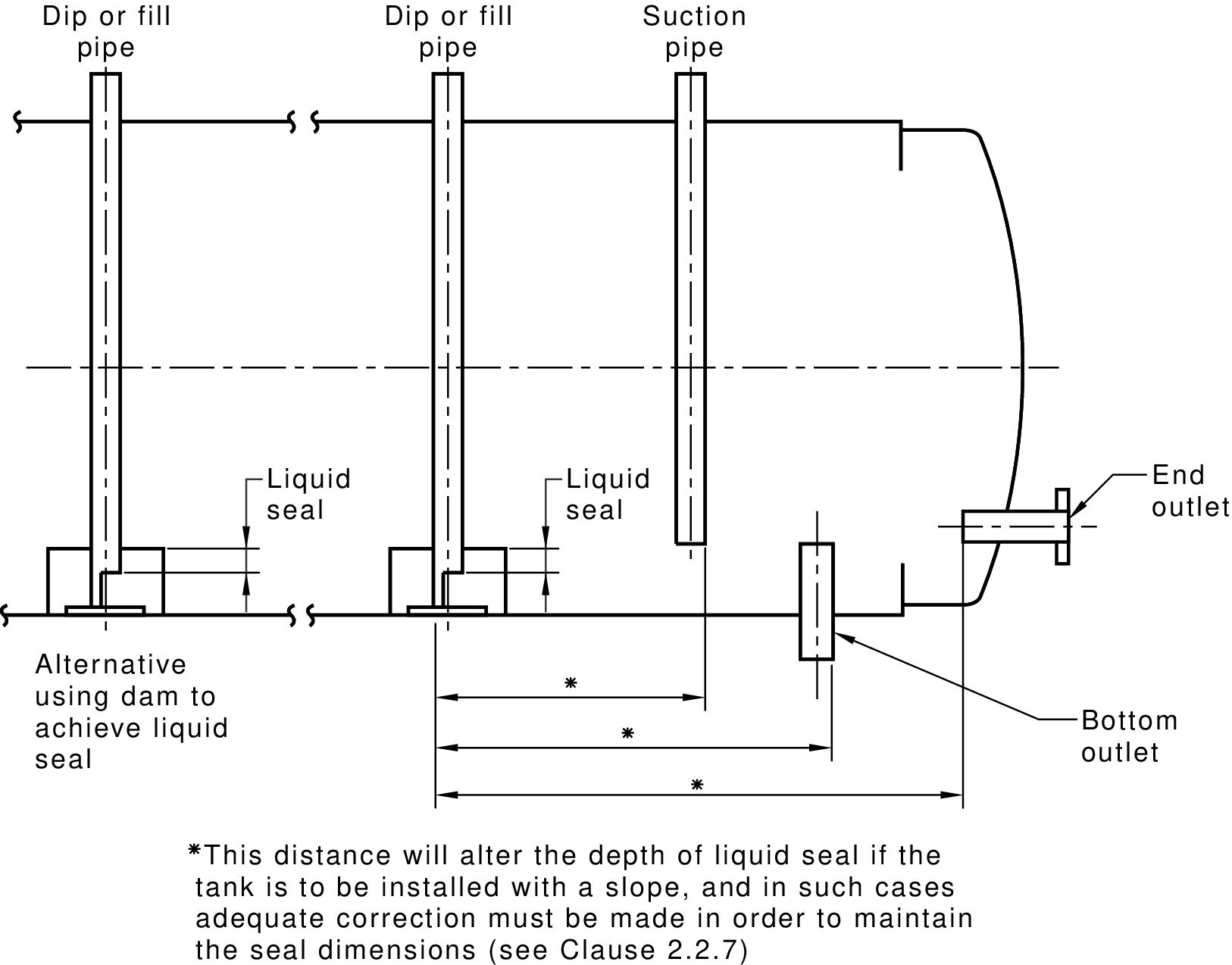
RULE Clause 2.2.7 Liquid seal PROVIDES
clause 2.2.7 is satisfied ONLY IF
the tank is a Category 1 tank OR
the tank does not have a fill pipe, suction pipe or dip pipe that
enters through the top of the tank OR
all fill pipes, suction pipes and dip pipes are not likely to be opened to
atmosphere at some time during normal filling OR
all fill pipes, suction pipes and dip pipes are provided with a liquid
seal sufficient to ensure that the lower end of the pipe is submerged in
at least 25 mm of liquid at all times after the initial filling.
IF the tank has a fill pipe, suction pipe or dip pipe that enters through the
top of the tank THEN
Figure 2.1 shows typical arrangements for liquid seals
/* FIGURE 2.1 LIQUID SEAL PROVISIONS */
RULE Clause 2.2.8 Access ladders and structures PROVIDES
clause 2.2.8 is satisfied ONLY IF
the tank does not have an access structure OR
all access structures comply with AS 1657 AND
the access structure is not attached to the tank AND/OR
the design or the access structure is such that there is no differential
movement between the tank and the structure
GOAL RULE Clause 2.3 Liquid Level Indication PROVIDES
the liquid level indication requirements set out in clause 2.3 are satisfied
ONLY IF
clause 2.3.1 is satisfied AND
clause 2.3.2 is satisfied AND
clause 2.3.3 is satisfied
RULE Clause 2.3.1 General PROVIDES
clause 2.3.1 is satisfied ONLY IF
the tank has a means of ascertaining the level of liquid within it AND
the indicator is not of a type designed for reading at a remote
location AND/OR
additional facilities for checking the accuracy of the level of liquid in
the tank is provided AND
the maximum permitted filling level is indicated on a gauge
IF clause 2.3.1 is satisfied THEN
any change to the contents of the tank may alter the maximum permitted
filling level AND
acceptable types of indicator are float gauges, hydrostatic pressure
gauges, dipsticks, dip tapes or sight tubes (gauge glasses)
RULE Clause 2.3.2 Dipsticks PROVIDES
clause 2.3.2 is satisfied ONLY IF
a dipstick system is not used OR
clause 2.3.2(a) is satisfied AND
clause 2.3.2(b) is satisfied AND
clause 2.3.2(c) is satisfied
RULE Clause 2.3.2(a) PROVIDES
clause 2.3.2(a) is satisfied ONLY IF
the tank is not an above-ground tank OR
the opening uses a common dip and vent OR
the opening has a cap that is liquid-tight and vapour-tight
RULE Clause 2.3.2(b) PROVIDES
clause 2.3.2(b) is satisfied ONLY IF
a dipstick is not used for measurement OR
the dipstick does not contact the bottom of the tank OR
a tubular dipstick guide is provided AND
the dipstick guide incorporates a pressure equalizer hole that connects
the upper end of the dip pipe with the upper tank space AND
the pressure equalizer hole is not more than 1.5 mm diameter AND/OR
the pressure equalizer hole is covered with anti-flash gauze not coarser
than 600 micro-mm mesh AND
the tank is a Category 1 tank AND/OR
the tank is a Category 2 tank AND/OR
a durable striker pad is attached firmly to the tank bottom below the
dip opening
RULE Clause 2.3.2(c) PROVIDES
clause 2.3.2(c) is satisfied ONLY IF
a dipstick is not used for measurement OR
the tank is not intended to contain flammable liquids OR
the dipstick is made of non-ferrous metal
RULE Clause 2.3.3 Sight tubes PROVIDES
clause 2.3.3 is satisfied ONLY IF
the tank is not intended to contain flammable liquids OR
the tank does not have a sight tube or gauge glass OR
the use of a sight tube or gauge glass is not avoidable AND
clause 2.3.3(a) is satisfied AND
clause 2.3.3(b) is satisfied AND
clause 2.3.3(c) is satisfied
RULE Clause 2.3.3(a) PROVIDES
clause 2.3.3(a) is satisfied ONLY IF
an adequate protective guard is provided for the sight tube
RULE Clause 2.3.3(b) PROVIDES
clause 2.3.3(b) is satisfied ONLY IF
the material of the sight tube is impervious to the liquid being stored AND
the material of the sight tube is compatible with the liquid being stored
RULE Clause 2.3.3(c) PROVIDES
clause 2.3.3(c) is satisfied ONLY IF
there is a self-closing shut-off valve provided on any connection leg that
is below the liquid level
GOAL RULE Clause 2.4 Filling Provisions PROVIDES
the filling requirements set out in clause 2.4 are satisfied ONLY IF
clause 2.4.1 is satisfied AND
clause 2.4.2 is satisfied AND
clause 2.4.3 is satisfied AND
clause 2.4.4 is satisfied
RULE Clause 2.4.1 General PROVIDES
clause 2.4.1 is satisfied ONLY IF
the tank has a suitable means of filling AND
the means of filling tank takes account the intended filling method AND
the means of filling the tank takes into account the location of the fill
point in relation to the tank
IF clause 2.4.1 is satisfied THEN
the means of filling the tank should be agreed between the purchaser and
supplier of the tank AND
for a top-filled tank, a weatherproof cap, cover or plug should be
provided with the tank
RULE Clause 2.4.2 Fill pipe PROVIDES
clause 2.4.2 is satisfied ONLY IF
BEGIN
the tank is a Category 1 tank AND/OR
the fill provision for the tank is such that the liquid flows through
a fully enclosed pipe to a discharge point that is not more than one
pipe diameter above the bottom of the tank
END AND BEGIN
the tank is not filled from the top AND/OR
an extension pipe is used, in order to comply with this requirement
END
IF clause 2.4.2 is satisfied AND
the tank is a vertical tank AND
the side entry of the tank is reinforced THEN
the discharge point should not be more than 150 mm from the tank bottom AND
the discharge point may be high enough to accommodate the reinforcing
ring AND
This requirement is intended to reduce splashing during filling, which
could result in the generation of static electricity, is minimized.
See AS/NZS 1020.
RULE Clause 2.4.3 Pressure equalization PROVIDES
clause 2.4.3 is satisfied ONLY IF
the tank does not have a fill pipe that fills downwards into the tank OR
the fill pipe incorporates a pressure equalizer hole that connects the
upper end of the pipe with the upper tank space AND
the pressure equalizer hole is not more than 1.5 mm diameter OR
the pressure equalizer hole is covered with anti-flash gauze not
coarser than 600 micro metre mesh
RULE Clause 2.4.4 High-head filling PROVIDES
clause 2.4.4 is satisfied ONLY IF
the height of the fill point is not above the tank OR
the pressure on the tank will not exceed the test pressures described in
Clause 2.8 OR
clause 2.4.4(a) is satisfied OR
clause 2.4.4(b) is satisfied
RULE Clause 2.4.4(a) PROVIDES
clause 2.4.4 is satisfied ONLY IF
the tank incorporates a provision to prevent the liquid level rising
above the full level
RULE Clause 2.4.4(b) PROVIDES
clause 2.4.4(b) is satisfied ONLY IF
the tank is designed and tested to withstand the additional pressure of
a liquid-full filling extension
GOAL RULE Clause 2.5 Draining and Normal Draw-Off PROVIDES
the draining and draw-off requirements set out in clause 2.5 are satisfied
ONLY IF
it is possible to remove all of the tank’s liquid contents, without
moving the tank from its installed position AND
the drain provision draws from the lowest point of the tank AND
the drain is not separate from the liquid draw-off pipe AND/OR
the drain is located as far as possible from the draw-off pipe AND
the conditions of installation are such that draining by gravity through a
bottom outlet can be provided AND/OR
there is a facility for the insertion of a suction spear though a fill
pipe or other opening (e.g. an underground tank)
GOAL RULE Clause 2.6 Manholes PROVIDES
the manhole requirements set out in clause 2.6 are satisfied ONLY IF
the tank does not have a manhole OR
clause 2.6.1 is satisfied AND
clause 2.6.2 is satisfied AND
clause 2.6.3 is satisfied AND
clause 2.6.4 is satisfied
RULE Clause 2.6.1 General PROVIDES
clause 2.6.1 is satisfied ONLY IF
the manhole is provided when specified by the tank purchaser
IF clause 2.6.1 is satisfied THEN
a manhole is not essential for tank safety, but may be convenient
during construction, or for the maintenance, cleaning or inspection of the
tank and any equipment inside it
RULE Clause 2.6.2 Size of manholes PROVIDES
clause 2.6.2 is satisfied ONLY IF
breathing apparatus will be required for personnel entering the tank AND
the diameter of the manhole is at least 600 mm in diameter OR
clause 2.6.2(a) is satisfied OR
clause 2.6.2(b) is satisfied OR
clause 2.6.2(c) is satisfied
RULE Clause 2.6.2(a) PROVIDES
clause 2.6.2(a) is satisfied ONLY IF
the manhole is elliptical AND
the size of the manhole is greater than or equal to 450 mm x 400 mm
RULE Clause 2.6.2(b) PROVIDES
clause 2.6.2(b) is satisfied ONLY IF
the manhole is circular AND
the diameter of the manhole is greater than or equal to 450 mm
RULE Clause 2.6.2(c) PROVIDES
clause 2.6.2(c) is satisfied ONLY IF
the manhole neck is less than 200 mm high OR
the diameter of the manhole is at least 600 mm
RULE Clause 2.6.3 Size of manholes PROVIDES
clause 2.6.3 is satisfied ONLY IF
the tank is not a vertical tank OR
the height of the tank LESS THAN 3m OR
the tank is not required to have a manhole near its top OR
a second manhole is provided near the bottom of the tank
IF clause 2.6.3 is satisfied THEN
if a single manhole is located near the bottom of the tank, no
other manhole is required unless specified by the purchaser
RULE Clause 2.6.4 Manhole covers PROVIDES
clause 2.6.4 is satisfied ONLY IF
the manhole has a cover that is vapour-tight and liquid-tight at the test
pressure
GOAL RULE Clause 2.7 Tank Vents PROVIDES
the vent requirements set out in clause 2.7 are satisfied ONLY IF
clause 2.7.1 is satisfied AND
clause 2.7.2 is satisfied AND
clause 2.7.3 is satisfied
RULE Clause 2.7.1 General PROVIDES
clause 2.7.1 is satisfied ONLY IF
the tank incorporates a provision for the vapour space above the liquid
to vent to atmosphere AND
the tank is a Category 1 tank AND/OR
the vent is separate from the fill orifice AND
clause 2.7.1(a) is satisfied OR
clause 2.7.1(b) is satisfied OR
clause 2.7.1(c) is satisfied
RULE Clause 2.7.1(a) Free venting PROVIDES
clause 2.7.1(a) is satisfied ONLY IF
the vapour space is in contact with the atmosphere
without any intervening valves or other devices AND
the pressure above the liquid is substantially that of the surrounding
atmosphere
RULE Clause 2.7.1(b) Pressure-vacuum venting (PV vents) PROVIDES
clause 2.7.1(b) is satisfied ONLY IF
a control device~permits a positive or negative pressure within the tank
to reach a predetermined level before the pressure or vacuum is relieved
RULE Clause 2.7.1(c) Emergency venting PROVIDES
clause 2.7.1(c) is satisfied ONLY IF
excessive pressure build up in emergency conditions such as fire is relieved
by means of a pressure-relief device
RULE Clause 2.7.2 Size of vent PROVIDES
clause 2.7.2 is satisfied ONLY IF
the size of any free vent or pressure-vacuum vent is such that
pressure or vacuum resulting from filling or emptying or atmospheric
temperature change will not cause stresses greater than the
normal maximum design stress AND
clause 2.7.2(a) is satisfied AND
clause 2.7.2(b) is satisfied AND
clause 2.7.2(c) is satisfied
IF clause 2.7.2 is satisfied THEN
the design of the vent, and particularly its size, are dependent on
factors that relate to the specific installation AND
a tank manufacturer would not normally undertake to design and size the
vent without instructions from the purchaser
RULE Clause 2.7.2(a) PROVIDES
clause 2.7.2(a) is satisfied ONLY IF
the tank is not a Category 1 tank OR
the vent is not a free vent OR
the vent is not combined with a filler OR
the opening provides at least 600 mm2 of free vent area with the
nozzle inserted and 10 mm2 with the cap in place
RULE Clause 2.7.2(b) PROVIDES
clause 2.7.2(b) is satisfied ONLY IF
the vent is a separate free vent AND
the tank is not a Category 1 tank AND
the tank is not a Category 2 tank OR
the vent area is the equivalent of a 25 mm nominal internal diameter pipe
RULE Clause 2.7.2(c) PROVIDES
clause 2.7.2(c) is satisfied ONLY IF
the tank is a Category 1 tank OR
the tank is a Category 2 tank OR
the vent provision or the vent connection facilities are those specified
by the purchaser of the tank
RULE Clause 2.7.3 Vent terminal PROVIDES
clause 2.7.3 is satisfied ONLY IF
the vent is not a free vent OR
the discharge end of the free vent supplied as part of a tank is
protected from the ingress of foreign material, e.g. by a return bend
or a protective cap, cage, or fitting AND
the fitting does not reduce the required vent area AND
the discharge point of the free vent is higher than the filling point
of the tank and at least 150 mm above the tank top
GOAL RULE Clause 2.8 Testing PROVIDES
the testing requirements set out in clause 2.8 are satisfied ONLY IF
clause 2.8.1 is satisfied AND
clause 2.8.2 is satisfied AND
clause 2.8.3 is satisfied
RULE Clause 2.8.1 Leakage test PROVIDES
clause 2.8.1 is satisfied ONLY IF
the tank has been subjected to a leakage test before any painting,
coating, or similar treatment has been applied AND
the tank has been found to be sound and liquid-tight before being put into
service AND
BEGIN a hydrostatic test method has been used AND
clause 2.8.2 is satisfied END AND/OR
BEGIN an air test has been conducted AND
the tank is not a Category 3 tank AND
the tank is not a Category 6 tank AND
clause 2.8.3 is satisfied END
RULE Clause 2.8.2 Hydrostatic testing PROVIDES
clause 2.8.2 is satisfied ONLY IF
a hydrostatic test has not been carried out OR
the tank was in the orientation of its operation, i.e. vertical tanks shall be tested when vertical and horizontal tanks tested when horizontal AND
clause 2.8.2(a) is satisfied AND
clause 2.8.2(b) is satisfied AND
clause 2.8.2(c) is satisfied AND
clause 2.8.2(d) is satisfied AND
clause 2.8.2(e) is satisfied
IF clause 2.8.2 is satisfied THEN
any flat side or end may be supported during testing, provided that
the method of support does not inhibit the observation of any leak AND
the purchaser is free to specify higher test pressures, but the
design of the tank should be checked for its ability to withstand any
such pressures
RULE Clause 2.8.2(a) PROVIDES
clause 2.8.2(a) is satisfied ONLY IF
the tank is not a free-vented tank OR
the tank is not a Category 1 tank AND
the tank is not a Category 2 tank AND
the tank is not a Category 5 tank AND
the tank was filled with water AND
one metre of additional water head was applied AND
the tank filling or operating pressure does not exceed the equivalent of
1 m head above the top of the tank AND/OR
the test pressure was less than the maximum pressure plus 1 m head of water
RULE Clause 2.8.2(b) PROVIDES
clause 2.8.2(b) is satisfied ONLY IF
the tank is not a Category 3 tank OR
the tank is not a free-vented tank OR
clause 2.8.2(a) is satisfied AND
the additional head has been reduced to 150 mm
RULE Clause 2.8.2(c) PROVIDES
clause 2.8.2(c) is satisfied ONLY IF
the tank is not a Category 6 tank OR
the test pressure and procedure was in accordance with the Standard to
which the tank was built
RULE Clause 2.8.2(d) PROVIDES
clause 2.8.2(d) is satisfied ONLY IF
a pressure-vacuum or emergency vent is not to be used with the tank OR
clause 2.8.2(a) is satisfied AND
an additional 35 kPa of pressure has been used in the test
IF clause 2.8.2(d) is satisfied THEN
The purchaser is free to specify higher test pressures, but the design of the tank should be checked for its ability to withstand any such pressures.
RULE Clause 2.8.2(e) PROVIDES
clause 2.8.2(e) is satisfied ONLY IF
the test pressure was applied for sufficient time to allow any leaks to
develop and to be observed
RULE Clause 2.8.3 Air testing PROVIDES
clause 2.8.3 is satisfied ONLY IF
an air test has not been conducted OR
clause 2.8.3(a) is satisfied AND
clause 2.8.3(b) is satisfied AND
clause 2.8.3(c) is satisfied AND
clause 2.8.3(d) is satisfied AND
clause 2.8.3(e) is satisfied AND
clause 2.8.3(f) is satisfied AND
clause 2.8.3(g) is satisfied AND
clause 2.8.3(h) is satisfied
RULE Clause 2.8.3(a) PROVIDES
clause 2.8.3(a) is satisfied ONLY IF
the air test has been applied to a new tank AND
the air test has been applied at the manufacturer’s premises
RULE Clause 2.8.3(b) PROVIDES
clause 2.8.3(b) is satisfied ONLY IF
the air test pressure was such as to provide stress to a level
equivalent to that which would be caused by the appropriate hydrostatic
test AND
the air test pressure did not exceed 35 kPa
RULE Clause 2.8.3(c) PROVIDES
clause 2.8.3(c) is satisfied ONLY IF
the source of supply for the air test does not have a pressure greater
than 35 kPa OR
the pressure from the source of supply for the air test was reduced by
means of a pressure-reducing device AND
a pressure gauge, safety valve, or hydrostatic pressure-relieving device,
and a pressure release cock was fitted on the low pressure side
RULE Clause 2.8.3(d) PROVIDES
clause 2.8.3(d) is satisfied ONLY IF
the tank is not to be filled from a filling point more than 1 m above
the tank shell OR
the air test was at the head resulting from the filling location, plus an
additional 1 m head of water
RULE Clause 2.8.3(e) PROVIDES
clause 2.8.3(e) is satisfied ONLY IF
the pressure-relieving device is capable of discharging the maximum
delivery of the pressure-reducing device without rise in pressure beyond
110% of the test pressure
RULE Clause 2.8.3(f) PROVIDES
clause 2.8.3(f) is satisfied ONLY IF
the tank was not subjected to blows while under air pressure
RULE Clause 2.8.3(g) PROVIDES
clause 2.8.3(g) is satisfied ONLY IF
air for testing was introduced gradually and evenly until the test
pressure was reached
RULE Clause 2.8.3(h) PROVIDES
clause 2.8.3(h) is satisfied ONLY IF
the test pressure was applied for sufficient time to allow any leaks
to develop and to be observed
GOAL RULE Clause 2.9 Handling and Transport PROVIDES
the handling and transport requirements set out in clause 2.9 are satisfied
ONLY IF
the tank could not suffer damage because of stresses caused by handling
and transportation AND/OR
the tank is provided with adequate supports and stays to protect it
until it has been installed
IF the handling and transport requirements set out in clause 2.9 are
satisfied THEN
lifting lugs may be provided
GOAL RULE Clause 2.10 Tanks with Fire-Rated Coverings PROVIDES
IF the tank has a fire-rated covering THEN
the fire-rated coverings requirements set out in clause 2.10 are satisfied
ONLY IF
the tank has a fire-rated covering AND BEGIN
the tank is a 'vaulted' tank AND
the tank complies with UL 2085 AND/OR
the tank has been approved by Underwriters Laboratories (UL) to the
equivalent of UL 2085 to the equivalent of US fire rating AND/OR
the tank has been approved by Factory Mutual (FM) to the
equivalent of UL 2085 to the equivalent of US fire rating END OR
the fire-rated covering is satisfied
GOAL RULE Section 3 Requirements for Specific Categories of Tanks PROVIDES
section 3 is satisfied ONLY IF
clause 3.2 is satisfied AND
clause 3.3 is satisfied AND
clause 3.4 is satisfied AND
clause 3.5 is satisfied AND
clause 3.6 is satisfied AND
clause 3.7 is satisfied
GOAL RULE Clause 3.1 Scope of Section PROVIDES
Section 3 sets out requirements for tanks, specific to their category
as given in Clause 1.3
GOAL RULE Clause 3.2 Category 1 Tanks PROVIDES
clause 3.2 is satisfied ONLY IF
the tank is not a Category 1 tank OR
clause 3.2.1 is satisfied AND
clause 3.2.2 is satisfied
RULE Clause 3.2.1 Size limitation PROVIDES
clause 3.2.1 is satisfied ONLY IF
the capacity of the tank LESSEQUAL 1200l
RULE Clause 3.2.2 Material PROVIDES
clause 3.2.2 is satisfied ONLY IF
BEGIN the tank is constructed of commercial grade low carbon steel AND
the material of construction of the tank is not less than 1.6mm OR
the tank is constructed of stainless steel AND
the material of construction of the tank is not less than 1.2mm END AND
the tank is made so that when completely filled in service no flat side
shall bulge by an amount greater than 2% of the lesser dimension of that
side
GOAL RULE Clause 3.3 Category 2 Tanks PROVIDES
clause 3.3 is satisfied ONLY IF
the tank is not a Category 2 tank OR
clause 3.3.1 is satisfied AND
clause 3.3.2 is satisfied
RULE Clause 3.3.1 Size limitation PROVIDES
clause 3.3.1 is satisfied ONLY IF
the capacity of the tank LESSEQUAL 2500l
RULE Clause 3.3.2 Material PROVIDES
clause 3.3.2 is satisfied ONLY IF
BEGIN the tank is constructed of commercial grade low carbon steel AND
the material of construction of the tank is not less than 2mm OR
the tank is constructed of stainless steel AND
the material of construction of the tank is not less than 1.6mm END AND
the tank is not a vertical tank AND/OR BEGIN
the tank is constructed of commercial grade low carbon steel AND
the bottom is not less than 3 mm nominal thickness OR
the tank is constructed of stainless steel AND
the bottom is not less than 2.5 mm nominal thickness END
GOAL RULE Clause 3.4 Category 3 Tanks PROVIDES
clause 3.4 is satisfied ONLY IF
the tank is not a Category 3 tank OR
clause 3.4.1 is satisfied AND
clause 3.4.2 is satisfied
RULE Clause 3.4.1 Material PROVIDES
clause 3.4.1 is satisfied ONLY IF
the material of construction of the tank is greater than the nominal
thickness given in Table 3.1
IF the tank is constructed of commercial grade low carbon steel THEN
thicknesses are empirical, based on the assumptions given in Clause 1.1 AND
tanks that are rectangular or of other unconventional shape should be
treated with caution because of the design problems involved
RULE Clause 3.4.2 Plate stiffness PROVIDES
clause 3.4.2 is satisfied ONLY IF
Any rectangular tanks shall be made so that when completely filled in service,
no side shall bulge by an amount greater than 2% of the lesser dimension
of that side.
NUMBER the minimum thickness of material for the tank UNIT mm
NUMBER the minimum thickness of material for the tank in Table 3.1 UNIT mm
NUMBER the maximum height for the base minimum thickness UNIT metres
NUMBER the multiplier for each metre of height UNIT mm
INTEGER the extra height UNIT none
NUMBER the additional thickness UNIT mm
NUMBER the base minimum thickness of material for the tank UNIT mm
RULE Table 3.1 Thickness of Material for Category 3 Rectangular Tanks
PROVIDES
Table 3.1 applies ONLY IF
the tank is a rectangular tank AND
the tank is a Category 3 tank AND
the capacity of the tank GREATER THAN 5000l AND/OR
the tank is constructed of low carbon steel AND/OR
the tank is constructed of stainless steel
IF Table 3.1 applies THEN BEGIN
IF the capacity of the tank GREATER THAN 5000l THEN
each flat surface of the tank shall be individually designed for the
pressure to be withstood
ELSE BEGIN
IF the tank is constructed of low carbon steel THEN BEGIN
IF the capacity of the tank LESSEQUAL 50l THEN
the base minimum thickness of material for the tank IS 0.8mm
ELSE IF the capacity of the tank LESSEQUAL 250l THEN
the base minimum thickness of material for the tank IS 1.0mm
ELSE IF the capacity of the tank LESSEQUAL 500l THEN
the base minimum thickness of material for the tank IS 1.6mm
ELSE IF the capacity of the tank LESSEQUAL 1200l THEN
the base minimum thickness of material for the tank IS 3.0mm
ELSE IF the capacity of the tank LESSEQUAL 5000l THEN
the base minimum thickness of material for the tank IS 5.0mm
END
ELSE IF the tank is constructed of stainless steel THEN BEGIN
IF the capacity of the tank LESSEQUAL 50l THEN
the base minimum thickness of material for the tank IS 0.6mm
ELSE IF the capacity of the tank LESSEQUAL 250l THEN
the base minimum thickness of material for the tank IS 0.8mm
ELSE IF the capacity of the tank LESSEQUAL 500l THEN
the base minimum thickness of material for the tank IS 1.0mm
ELSE IF the capacity of the tank LESSEQUAL 1200l THEN
the base minimum thickness of material for the tank IS 2.5mm
ELSE IF the capacity of the tank LESSEQUAL 5000l THEN
the base minimum thickness of material for the tank IS 4.5mm
END
IF the capacity of the tank LESSEQUAL 50l THEN BEGIN
the maximum height for the base minimum thickness IS 0.5m
ASSERT the multiplier for each metre of height IS 0.5mm
END ELSE IF the capacity of the tank LESSEQUAL 500l THEN BEGIN
the maximum height for the base minimum thickness IS 1.0m
ASSERT the multiplier for each metre of height IS 0.5mm
END ELSE BEGIN
the maximum height for the base minimum thickness IS 1.5m
ASSERT the multiplier for each metre of height IS 1.5mm
END
the minimum thickness of material for the tank in Table 3.1 IS
the base minimum thickness of material for the tank
IF the height of the tank GREATER THAN the maximum height for the
base minimum thickness THEN BEGIN
the extra height IS the height of the tank MINUS
the maximum height for the base minimum thickness /* PLUS 1 */
ASSERT the additional thickness IS
the extra height TIMES
the multiplier for each metre of height
ASSERT the minimum thickness of material for the tank in
Table 3.1 IS the minimum thickness of material for the tank
in Table 3.1 PLUS the additional thickness
END
END
the material of construction of the tank is greater than the nominal
thickness given in Table 3.1 ONLY IF
the minimum thickness of material for the tank GREATEREQUAL
the minimum thickness of material for the tank in Table 3.1
END
GOAL RULE Clause 3.5 Category 4 Tanks PROVIDES
clause 3.5 is satisfied ONLY IF
the tank is not a Category 4 tank OR
clause 3.5.1 is satisfied AND
clause 3.5.2 is satisfied AND
clause 3.5.3 is satisfied AND
clause 3.5.4 is satisfied
RULE Clause 3.5.1 Material PROVIDES
clause 3.5.1 is satisfied ONLY IF
the material of construction of the tank is greater than the nominal
thickness given in Table 3.2 AND
the length of the tank LESSEQUAL the diameter of the tank TIMES 5
IF clause 3.5.1 is satisfied THEN BEGIN
thicknesses are empirical, based on certain assumptions that are
outlined in Clause 1.1.
IF the tank is an underground tanks for service station use AND
the tank is constructed from glass-fibre-reinforced plastics THEN
the tank must comply with UL 1316
END
NUMBER the diameter of the tank UNIT metres
NUMBER the length of the tank UNIT metres
NUMBER the minimum thickness of material for the tank in Table 3.2 UNIT mm
RULE Table 3.2 Thickness, Shells and Ends for Horizontal Cylindrical
Tanks for Category 4 PROVIDES
Table 3.2 applies ONLY IF
the tank is a cylindrical tank AND
the tank is a Category 4 tank AND
the tank is constructed of low carbon steel AND/OR
the tank is constructed of stainless steel AND
the diameter of the tank LESSEQUAL 3.75m AND
the length of the tank LESSEQUAL the diameter of the tank TIMES 5
IF Table 3.2 applies THEN BEGIN
IF the tank is constructed of low carbon steel THEN BEGIN
IF the diameter of the tank LESSEQUAL 1.53m THEN
the minimum thickness of material for the tank in Table 3.2 IS 3mm
ELSE IF the diameter of the tank LESSEQUAL 2.20m THEN
the minimum thickness of material for the tank in Table 3.2 IS 5mm
ELSE IF the diameter of the tank LESSEQUAL 2.75m THEN
the minimum thickness of material for the tank in Table 3.2 IS 6mm
ELSE IF the diameter of the tank LESSEQUAL 3.75m THEN
the minimum thickness of material for the tank in Table 3.2 IS 8mm
END ELSE IF the tank is constructed of stainless steel THEN BEGIN
IF the diameter of the tank LESSEQUAL 1.53m THEN
the minimum thickness of material for the tank in Table 3.2 IS 2.5mm
ELSE IF the diameter of the tank LESSEQUAL 2.20m THEN
the minimum thickness of material for the tank in Table 3.2 IS 4mm
ELSE IF the diameter of the tank LESSEQUAL 2.75m THEN
the minimum thickness of material for the tank in Table 3.2 IS 5mm
ELSE IF the diameter of the tank LESSEQUAL 3.75m THEN
the minimum thickness of material for the tank in Table 3.2 IS 6mm
END
the material of construction of the tank is greater than the nominal
thickness given in Table 3.2 ONLY IF
the minimum thickness of material for the tank GREATEREQUAL
the minimum thickness of material for the tank in Table 3.2
END
RULE Clause 3.5.2 Tank Ends PROVIDES
clause 3.5.2 is satisfied ONLY IF
Table 3.3 does not apply OR
all conical and dished ends are formed to a height not less than that
given in Table 3.3 AND
the tank does not have a flat end OR
all flat ends are stayed or stiffened in accordance with AS 1210
RULE Table 3.3 Minimum Height of Dished or Conical Ends for Tanks for
Category 4 PROVIDES
Table 3.3 applies ONLY IF
the tank is a Category 4 tank AND
the tank has one or more conical or dished ends AND
the diameter of the tank LESSEQUAL 3.75m
IF Table 3.3 applies THEN BEGIN
IF the diameter of the tank LESSEQUAL 1.53m THEN
the minimum height of conical or dished ends in Table 3.3 IS 40mm
ELSE IF the diameter of the tank LESSEQUAL 2.20m THEN
the minimum height of conical or dished ends in Table 3.3 IS 70mm
ELSE IF the diameter of the tank LESSEQUAL 2.75m THEN
the minimum height of conical or dished ends in Table 3.3 IS 110mm
ELSE IF the diameter of the tank LESSEQUAL 3.75m THEN
the minimum height of conical or dished ends in Table 3.3 IS 200mm
ASSERT all conical and dished ends are formed to a height not less than
that given in Table 3.3 ONLY IF
the minimum height of conical or dished ends GREATEREQUAL
the minimum height of conical or dished ends in Table 3.3
ASSERT the dished height does not include the straight length of any
flange, i.e. dimension F of Figure 3.1 is additional to the dished height
END
RULE Clause 3.5.3 Placing of supports PROVIDES
clause 3.5.3 is satisfied ONLY IF
the location of a support in relation to the end of the tank is such
that the shell will not fail due to loading in the vicinity of the
support
IF clause 3.5.3 is satisfied THEN
AS 1210 provides methods for calculating stresses at supports
RULE Clause 3.5.4 Construction PROVIDES
clause 3.5.4 is satisfied ONLY IF
the tank does not have any welded joints OR
clause 3.5.4(a) is satisfied AND
clause 3.5.4(b) is satisfied AND
clause 3.5.4(c) is satisfied AND
clause 3.5.4(d) is satisfied
RULE Clause 3.5.4(a) PROVIDES
clause 3.5.4(a) is satisfied ONLY IF
all longitudinal shell joints are butt joints (see Figure 3.1(a))
RULE Clause 3.5.4(b) PROVIDES
clause 3.5.4(b) is satisfied ONLY IF
the tank does not have circumferential welded joints OR
the tank does not incorporate a pressure-vacuum venting and the pressure
setting of more than 14 kPa OR
all circumferential joints are butt joints or double-welded lap joints
RULE Clause 3.5.4(c) PROVIDES
clause 3.5.4(c) is satisfied ONLY IF
all dished internal bulkheads within the tank are welded on at least one
side
RULE Clause 3.5.4(d) PROVIDES
clause 3.5.4(d) is satisfied ONLY IF
the tank does not have circumferential welded joints OR
clause 3.5.4(b) is satisfied OR
the purchaser specifically requires lap joints to be seal-welded on the
inside OR
the welded joints meet the requirements of Figure 3.1
GOAL RULE Clause 3.6 Category 5 Tanks PROVIDES
clause 3.6 is satisfied ONLY IF
the tank is not a Category 5 tank OR
clause 3.6.1 is satisfied AND
clause 3.6.2 is satisfied AND
clause 3.6.3 is satisfied AND
clause 3.6.4 is satisfied
RULE Clause 3.6.1 Material PROVIDES
clause 3.6.1 is satisfied ONLY IF
the tank is not a Category 5 tank OR
the material of construction meets the requirements of Table 3.4
IF clause 3.6.1 is satisfied THEN
Thicknesses are empirical, based on the assumptions outlined in Clause 1.1
RULE Clause 3.6.2 Flat tank bottom PROVIDES
clause 3.6.2 is satisfied ONLY IF
the tank is intended to be installed so that it rests on and is evenly
and adequately supported over its entire bottom area OR
the bottom is not flat OR
the tank is supported by means of a projecting rim, skirt, or legs
without any other support for the bottom AND
the bottom is stayed and stiffened in accordance with AS 1210
RULE Clause 3.6.3 Bolting down PROVIDES
clause 3.6.3 is satisfied ONLY IF
clause 3.6.3(a) does not apply AND
clause 3.6.3(b) does not apply OR
the tank incorporates provisions for bolting down, sufficient to withstand
the forces involved
RULE Clause 3.6.3(a) Bolting down PROVIDES
clause 3.6.3(a) applies ONLY IF
wind loadings could dislodge or overturn the empty tank (see AS/NZS 1170.2)
RULE Clause 3.6.3(b) Bolting down PROVIDES
clause 3.6.3(b) applies ONLY IF
an uplift force on a tank roof (due to the pressure setting of a vent) is
greater than the mass of the roof and shell
RULE Table 3.4 Thickness, Shells and Ends for Cylindrical Vertical
Tanks of Category 5 PROVIDES
Table 3.4 applies ONLY IF
the tank is a Category 5 tank AND
the tank is a cylindrical tank AND
the tank is a vertical tank AND
the diameter of the tank GREATER 4.5m AND/OR
the tank is constructed of low carbon steel AND/OR
the tank is constructed of stainless steel
IF Table 3.4 applies THEN BEGIN
IF the diameter of the tank GREATER THAN 4.5m THEN
the tank should be designed as a Category 6 tank
ELSE IF the tank is constructed of low carbon steel THEN BEGIN
IF the diameter of the tank LESSEQUAL 1.53m THEN
the minimum shell thickness IS 3mm
ELSE IF the diameter of the tank LESSEQUAL 2.20m THEN
the minimum shell thickness IS 5mm
ELSE IF the diameter of the tank LESSEQUAL 2.75m THEN
the minimum shell thickness IS 5mm
ELSE IF the diameter of the tank LESSEQUAL 3.75m THEN
the minimum shell thickness IS 6mm
ELSE IF the diameter of the tank LESSEQUAL 4.5m THEN
the minimum shell thickness IS 6mm
IF the bottom of the tank is flat THEN
the minimum bottom thickness IS 6mm
ELSE IF the bottom of the tank is dished or coned THEN BEGIN
IF the diameter of the tank LESSEQUAL 1.53m THEN
the minimum bottom thickness IS 3mm
ELSE IF the diameter of the tank LESSEQUAL 2.20m THEN
the minimum bottom thickness IS 5mm
ELSE IF the diameter of the tank LESSEQUAL 2.75m THEN
the minimum bottom thickness IS 6mm
ELSE IF the diameter of the tank LESSEQUAL 3.75m THEN
the minimum bottom thickness IS 8mm
ELSE IF the diameter of the tank LESSEQUAL 4.5m THEN
the minimum bottom thickness IS 10mm
END
IF the top of the tank is flat THEN BEGIN
IF the diameter of the tank LESSEQUAL 1.53m THEN
the minimum top thickness IS 3mm
ELSE IF the diameter of the tank LESSEQUAL 2.20m THEN
the minimum top thickness IS 5mm
ELSE IF the diameter of the tank LESSEQUAL 2.75m THEN
the minimum top thickness IS 5mm
ELSE IF the diameter of the tank LESSEQUAL 3.75m THEN
the minimum top thickness IS 6mm
ELSE IF the diameter of the tank LESSEQUAL 4.5m THEN
the minimum top thickness IS 6mm
END ELSE IF the top of the tank is dished or coned THEN BEGIN
IF the diameter of the tank LESSEQUAL 1.53m THEN
the minimum top thickness IS 3mm
ELSE IF the diameter of the tank LESSEQUAL 2.20m THEN
the minimum top thickness IS 3mm
ELSE IF the diameter of the tank LESSEQUAL 2.75m THEN
the minimum top thickness IS 5mm
ELSE IF the diameter of the tank LESSEQUAL 3.75m THEN
the minimum top thickness IS 5mm
ELSE IF the diameter of the tank LESSEQUAL 4.5m THEN
the minimum top thickness IS 5mm
END
END ELSE IF the tank is constructed of stainless steel THEN BEGIN
IF the diameter of the tank LESSEQUAL 1.53m THEN
the minimum shell thickness IS 2.5mm
ELSE IF the diameter of the tank LESSEQUAL 2.20m THEN
the minimum shell thickness IS 4mm
ELSE IF the diameter of the tank LESSEQUAL 2.75m THEN
the minimum shell thickness IS 4mm
ELSE IF the diameter of the tank LESSEQUAL 3.75m THEN
the minimum shell thickness IS 5mm
ELSE IF the diameter of the tank LESSEQUAL 4.5m THEN
the minimum shell thickness IS 5mm
IF the bottom of the tank is flat THEN
the minimum bottom thickness IS 6mm
ELSE IF the bottom of the tank is dished or coned THEN BEGIN
IF the diameter of the tank LESSEQUAL 1.53m THEN
the minimum bottom thickness IS 2.5mm
ELSE IF the diameter of the tank LESSEQUAL 2.20m THEN
the minimum bottom thickness IS 4mm
ELSE IF the diameter of the tank LESSEQUAL 2.75m THEN
the minimum bottom thickness IS 5mm
ELSE IF the diameter of the tank LESSEQUAL 3.75m THEN
the minimum bottom thickness IS 6mm
ELSE IF the diameter of the tank LESSEQUAL 4.5m THEN
the minimum bottom thickness IS 8mm
END
IF the top of the tank is flat THEN BEGIN
IF the diameter of the tank LESSEQUAL 1.53m THEN
the minimum top thickness IS 2.5mm
ELSE IF the diameter of the tank LESSEQUAL 2.20m THEN
the minimum top thickness IS 4mm
ELSE IF the diameter of the tank LESSEQUAL 2.75m THEN
the minimum top thickness IS 4mm
ELSE IF the diameter of the tank LESSEQUAL 3.75m THEN
the minimum top thickness IS 5mm
ELSE IF the diameter of the tank LESSEQUAL 4.5m THEN
the minimum top thickness IS 5mm
END ELSE IF the top of the tank is dished or coned THEN BEGIN
IF the diameter of the tank LESSEQUAL 1.53m THEN
the minimum top thickness IS 2.5mm
ELSE IF the diameter of the tank LESSEQUAL 2.20m THEN
the minimum top thickness IS 2.5mm
ELSE IF the diameter of the tank LESSEQUAL 2.75m THEN
the minimum top thickness IS 4mm
ELSE IF the diameter of the tank LESSEQUAL 3.75m THEN
the minimum top thickness IS 4mm
ELSE IF the diameter of the tank LESSEQUAL 4.5m THEN
the minimum top thickness IS 4mm
END
END
the material of construction meets the requirements of Table 3.4 ONLY IF
the top thickness of the tank GREATEREQUAL the minimum top
thickness AND
the bottom thickness of the tank GREATEREQAL the minimum bottom
thickness AND
the shell thickness of the tank GREATEREQUAL the minimum shell
thickness
ASSERT all thickness are nominal AND
flat bottoms are assumed to be fully supported over at least 60
percent of their area (see Clause 3.6.2) AND
dished or coned bottoms are assumed to be for tanks that rest on
peripheral legs, so that the bottoms have no support AND
tanks that are particularly tall, so that the liquid head is
high, should be checked in accordance with AS 1210 to verify the
adequacy of the shell and bottom thickness AND
the shell should also be checked for adequacy at the point of
attachment of legs
END ELSE
the material of construction does not meet the requirements of Table 3.4
RULE Clause 3.6.4 Welded joints PROVIDES
Any welded joint shall comply with the following requirements and
clause 3.6.4 is satisfied ONLY IF
the tank does not contain welded joints OR
clause 3.6.4(a) is satisfied AND
clause 3.6.4(b) is satisfied AND
clause 3.6.4(c) is satisfied
RULE Clause 3.6.4(a) Shell PROVIDES
clause 3.6.4(a) is satisfied ONLY IF
all longitudinal shell joints are butt joints AND
the welded joints meet the requirements of Figure 3.1
RULE Clause 3.6.4(b) Bottom PROVIDES
clause 3.6.4(b) is satisfied ONLY IF
the tank does not rest on the tank bottom AND/OR
the joint between the shell and the bottom is a double-sided fillet
joint AND
the tank is not on legs AND/OR
the joint between the shell and the bottom is either a butt joint or a
double-welded lap joint
IF clause 3.6.4(b) is satisfied THEN
any transverse seam across a tank bottom may be a single-welded lap
joint (with the weld inside) if the tank rests on the tank bottom, or a
butt joint or double-welded lap joint if the tank is on legs
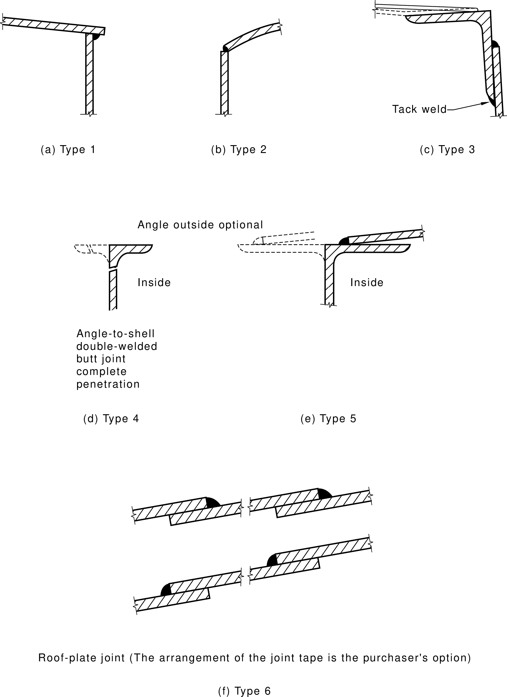
RULE Clause 3.6.4(c) Tank top PROVIDES
clause 3.6.4(c) is satisfied ONLY IF
the welded joints meet the requirements of Figure 3.1 AND/OR
the joint type illustrated in Figure 3.2 is used AND
the tank does not incorporate a pressure-vacuum venting and the pressure
setting of more than 14 kPa AND/OR BEGIN
the joint between the shell and the top is reinforced as illustrated in
Figure 3.2(c) AND
the design shall be in accordance with BS EN 14015 AND/OR
the diameter of the tank LESS THAN 3m AND/OR
the tank incorporates a dished and flanged end END
GOAL RULE Clause 3.7 Category 6 Tanks PROVIDES
clause 3.7 is satisfied ONLY IF
the tank is not a Category 6 tank OR
the tank complies fully with BS EN 14015, API 620, API 650, or other
equivalent Standard
IF clause 3.7 is satisfied THEN
where the Standard chosen makes reference to another Standard of its
country of origin, an Australian Standard may be substituted, provided that
the substitution is appropriate and both parties to the purchase contract
are agreeable AND
a list of preferred sizes for Category 6 tank diameters, in metric
dimensions, is given in BS EN 14015
GOAL RULE Figure 3.1 Typical joints for tanks PROVIDES
the welded joints meet the requirements of Figure 3.1 ONLY IF
the tank has a weld AND
Figure 3.1(a) is satisfied AND/OR
Figure 3.1(b) is satisfied AND/OR
Figure 3.1(c) is satisfied AND/OR
Figure 3.1(d) is satisfied AND/OR
Figure 3.1(e) is satisfied AND/OR
Figure 3.1(f) is satisfied
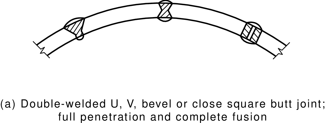
RULE Figure 3.1(a) PROVIDES
Figure 3.1(a) is satisfied ONLY IF
the weld is a double-welded U joint OR
the weld is a double-welded V joint OR
the weld is a double-welded bevel joint OR
the weld is a close square butt joint AND
the weld has full penetrated and complete fusion
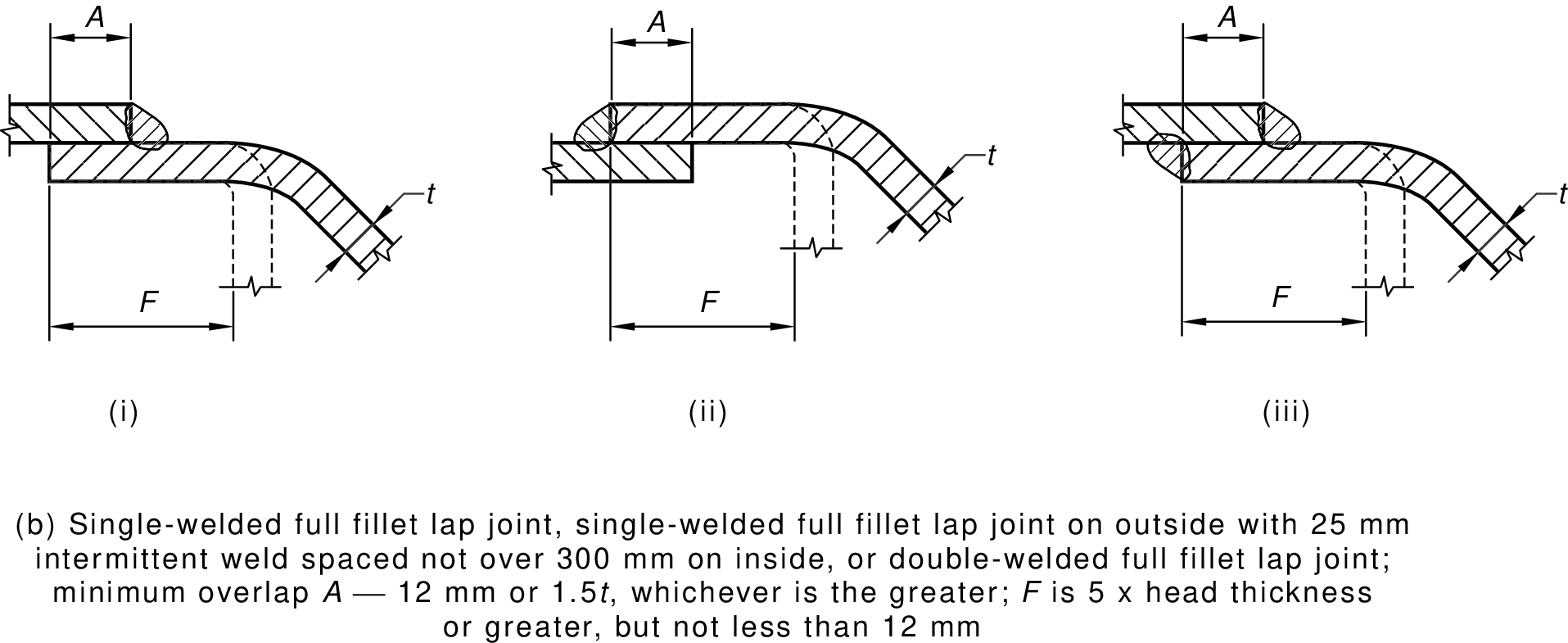
RULE Figure 3.1(b) PROVIDES
Figure 3.1(b) is satisfied ONLY IF
BEGIN
the weld is an inside single-welded full fillet lap joint OR
the weld is an outside single-welded full fillet lap joint AND
the joint has 25 mm intermitted welds spaced not over 300mm on the inside OR
the weld is a double-welded full fillet lap joint END AND
the minimum overlap distance of the two surfaces (A) is 12 mm or 1.5 t (the thickness of the shell) whichever is the greater AND
the flat distance up to the point at which the surface bends (F) is 5 times or greater than the head thickness, but not less than 12 mm
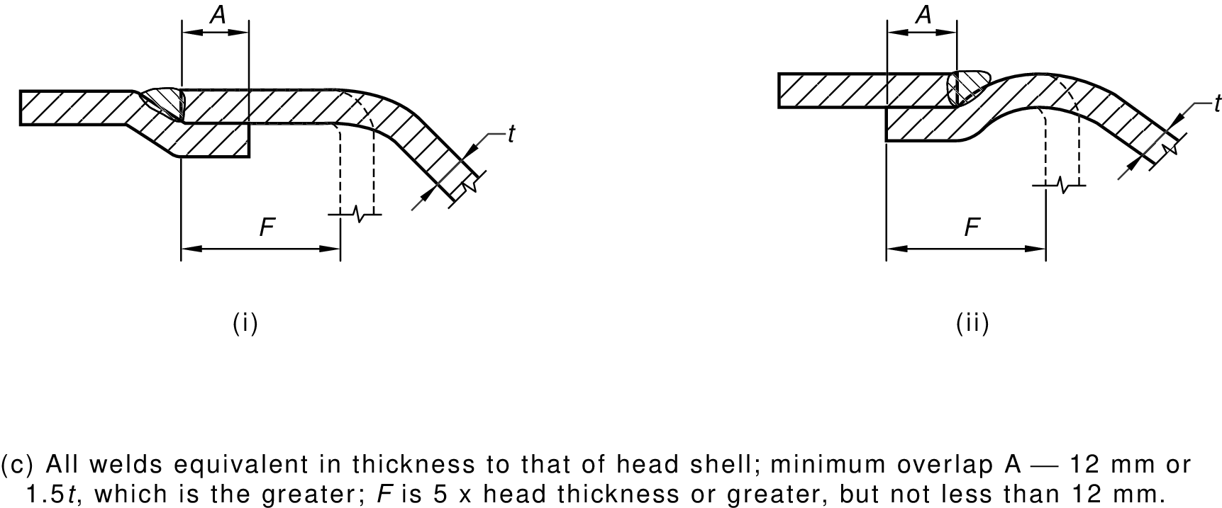
RULE Figure 3.1(c) PROVIDES
Figure 3.1(c) is satisfied ONLY IF
the weld is equivalent in thickness to that of the head shell AND
the minimum overlap distance of the two surfaces (A) is 12 mm or 1.5 t (the thickness of the shell) whichever is the greater AND
the flat distance up to the point at which the surface bends (F) is 5 times or greater than the head thickness, but not less than 12 mm OR
the distance up to the point at which the surface bends away from the direction of the curved welded surface (F) is 5 times or greater than the head thickness, but not less than 12 mm
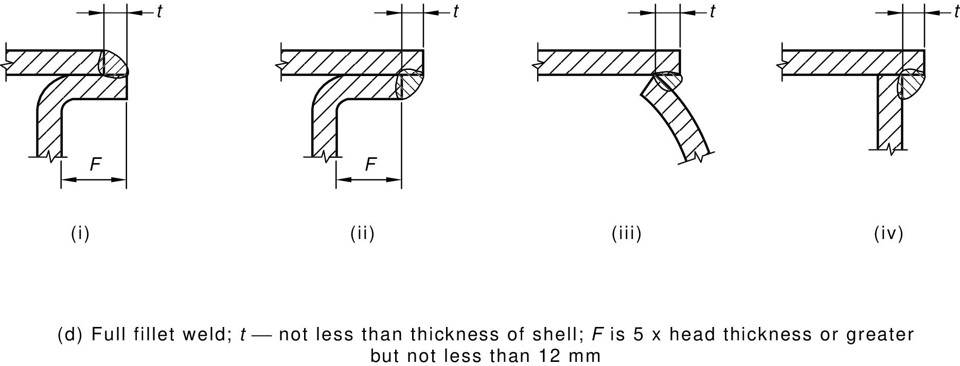
RULE Figure 3.1(d) PROVIDES
Figure 3.1(d) is satisfied ONLY IF
the weld is a full fillet weld AND
the thickness of the full fillet weld is equivalent in thickness to that of the shell
IF the weld joins two overlapping flat surfaces THEN
the flat distance up to the point at which the surface bends (F) is 5 times or greater than the head thickness, but not less than 12 mm
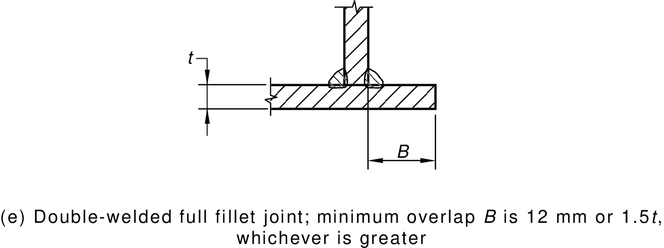
RULE Figure 3.1(e) PROVIDES
Figure 3.1(e) is satisfied ONLY IF
the weld is a double-welded full fillet joint AND
the minimum overlap distance (B) is 12 mm or 1.5 t (the thickness of the shell) whichever is the greater
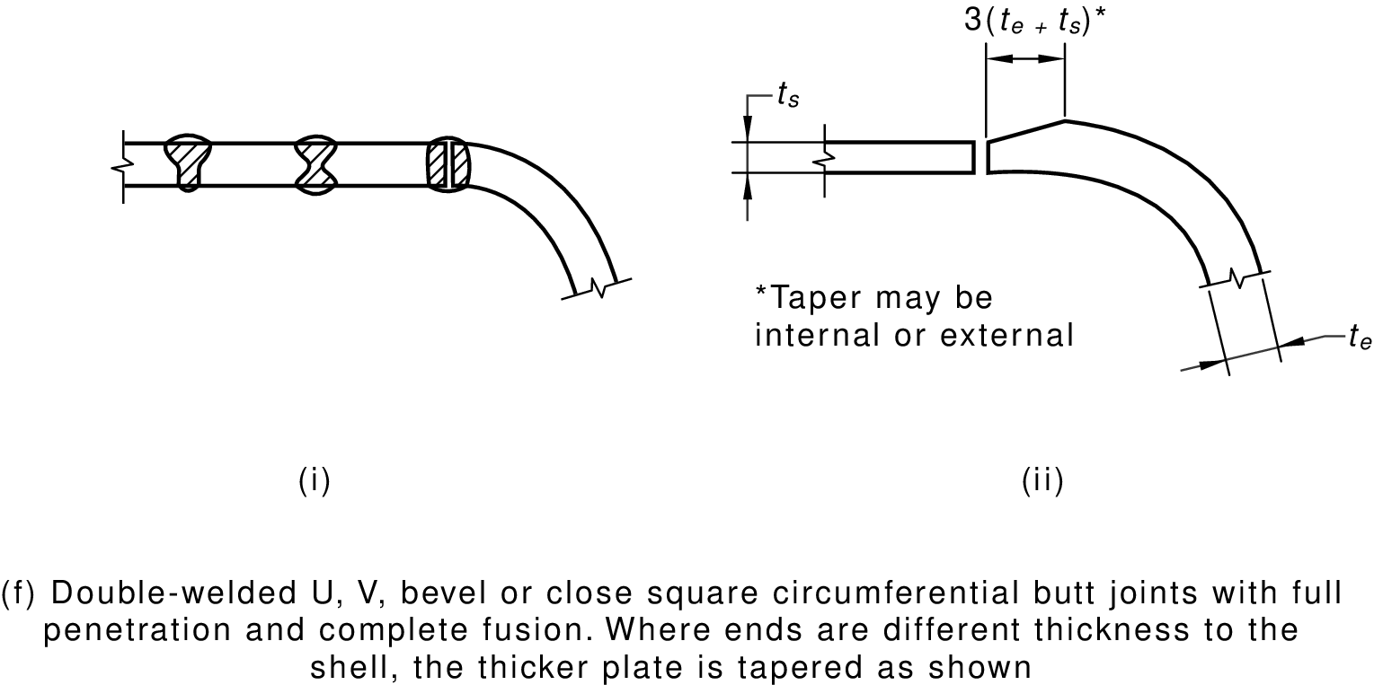
RULE Figure 3.1(f) PROVIDES
Figure 3.1(f) is satisfied ONLY IF
the weld is a double-welded U joint OR
the weld is a double-welded V joint OR
the weld is a double-welded bevel joint OR
the weld is a close square circumferential butt joint AND
the weld has full penetrated and complete fusion AND
the ends are different thicknesses to the shell AND
the distance of the taper is 3 times the (thickness of the wider shell plus the thickness of the thinner shell)
/*
FIGURE 3.2 VERTICAL TANKS—ROOF JOINTS
*/
GOAL RULE Appendix A Information to be Provided by the Purchaser
(Normative) PROVIDES
appendix A is satisfied ONLY IF
the purchaser has provided the tank manufacturer with such information
as is necessary to permit manufacture of the tank AND
the information listed in Appendix A(a) has been provided AND
the information listed in Appendix A(b) has been provided AND
the information listed in Appendix A(c) has been provided AND
the information listed in Appendix A(d) has been provided AND
the information listed in Appendix A(e) has been provided AND
the information listed in Appendix A(f) has been provided AND
the information listed in Appendix A(g) has been provided AND
the information listed in Appendix A(h) has been provided AND
the information listed in Appendix A(i) has been provided AND
the information listed in Appendix A(j) has been provided AND
the information listed in Appendix A(k) has been provided AND
the information listed in Appendix A(l) has been provided
RULE Appendix A(a) PROVIDES
the information listed in Appendix A(a) has been provided ONLY IF
the purchaser has specified whether the tank is to be above ground, or
wholly or partly buried
RULE Appendix A(b) PROVIDES
the information listed in Appendix A(b) has been provided ONLY IF
the purchaser has specified he type and nature of the filling provision
required
RULE Appendix A(c) PROVIDES
the information listed in Appendix A(c) has been provided ONLY IF
the purchaser has specified the test pressure, or the liquid head, or the
pressure of operation
RULE Appendix A(d) PROVIDES
the information listed in Appendix A(d) has been provided ONLY IF
the purchaser has specified the type and location of the draw-off
connection
RULE Appendix A(e) PROVIDES
the information listed in Appendix A(e) has been provided ONLY IF
the purchaser has specified the vent provision, i.e. the type, size,
capacity, provision for any vent extension
RULE Appendix A(f) PROVIDES
the information listed in Appendix A(f) has been provided ONLY IF
the purchaser has specified whether a manhole or manholes are required and
their location
RULE Appendix A(g) PROVIDES
the information listed in Appendix A(g) has been provided ONLY IF
the purchaser has specified whether a test certificate is required
RULE Appendix A(h) PROVIDES
the information listed in Appendix A(h) has been provided ONLY IF
the purchaser has specified whether calibration of tank or contents
indicator is required
RULE Appendix A(i) PROVIDES
the information listed in Appendix A(i) has been provided ONLY IF
the purchaser has specified any finishing or protective coatings required
RULE Appendix A(j) PROVIDES
the information listed in Appendix A(j) has been provided ONLY IF
the purchaser has specified the density of the liquid if it exceeds
1000 kg/m3
RULE Appendix A(k) PROVIDES
the information listed in Appendix A(k) has been provided ONLY IF
the purchaser has specified any special requirements regarding supports
RULE Appendix A(l) PROVIDES
the information listed in Appendix A(l) has been provided ONLY IF
the purchaser has specified the product to be stored
/*
* Common sense
*/
RULE Steel Tanks PROVIDES
the tank is a steel tank within the meaning of the Standard ONLY IF
the tank is constructed of commercial grade low carbon steel OR
the tank is constructed of stainless steel
FORWARD RULE Clause 1.3 Vertical / Horizontal Tanks PROVIDES
IF the tank is a vertical tank THEN
the tank is not a horizontal tank
FORWARD RULE Clause 1.3 Vertical / Horizontal Tanks PROVIDES
IF the tank is a horizontal tank THEN
the tank is not a vertical tank
FORWARD RULE Clause 1.3 Tank Shapes PROVIDES
IF the tank is a cylindrical tank THEN
the tank is not a rectangular tank
FORWARD RULE Clause 1.3 Tank Shapes PROVIDES
IF the tank is a rectangular tank THEN
the tank is not a cylindrical tank
FORWARD RULE Clause 1.3 Tank Shapes PROVIDES
IF the tank is a cylindrical tank OR the tank is a rectangular tank THEN
the tank is not an unconventional shape
FORWARD RULE Clause 1.3 Tank Shapes PROVIDES
IF the tank is a cylindrical tank AND the tank is a rectangular tank THEN
the tank is an unconventional shape
FORWARD RULE Clause 1.3 Tank Shapes PROVIDES
IF the tank is an unconventional shape THEN
the tank is not a cylindrical tank
FORWARD RULE Clause 1.3 Tank Shapes PROVIDES
IF the tank is an unconventional shape THEN
the tank is not a rectangular tank
/*
* Figures
*/
FACT Figure 2.1 shows typical arrangements for liquid seals
EXPLAIN AS Figure 2.1
 FACT all longitudinal shell joints are butt joints (see Figure 3.1(a))
EXPLAIN AS Figure 3.1(a)
FACT all longitudinal shell joints are butt joints (see Figure 3.1(a))
EXPLAIN AS Figure 3.1(a)
 FACT the weld is a double-welded U joint
EXPLAIN AS Figure 3.1(a)
FACT the weld is an inside single-welded full fillet lap joint
EXPLAIN AS Figure 3.1(b)
FACT the weld is a double-welded U joint
EXPLAIN AS Figure 3.1(a)
FACT the weld is an inside single-welded full fillet lap joint
EXPLAIN AS Figure 3.1(b)
 FACT the weld is equivalent in thickness to that of the head shell
EXPLAIN AS Figure 3.1(c)
FACT the weld is equivalent in thickness to that of the head shell
EXPLAIN AS Figure 3.1(c)
 FACT the weld is a full fillet weld
EXPLAIN AS Figure 3.1(d)
FACT the weld is a full fillet weld
EXPLAIN AS Figure 3.1(d)
 FACT the weld is a double-welded full fillet joint
EXPLAIN AS Figure 3.1(e)
FACT the weld is a double-welded full fillet joint
EXPLAIN AS Figure 3.1(e)
 FACT the weld is a close square circumferential butt joint
EXPLAIN AS Figure 3.1(f)
FACT the weld is a close square circumferential butt joint
EXPLAIN AS Figure 3.1(f)
 FACT the joint type illustrated in Figure 3.2
EXPLAIN AS Figure 3.2
FACT the joint type illustrated in Figure 3.2
EXPLAIN AS Figure 3.2
 FACT the joint between the shell and the top is reinforced as illustrated in Figure 3.2(c)
EXPLAIN AS Figure 3.2
INCLUDE http://austlii.community/wiki/DataLex/SteelTanksLinksCB
FACT the joint between the shell and the top is reinforced as illustrated in Figure 3.2(c)
EXPLAIN AS Figure 3.2
INCLUDE http://austlii.community/wiki/DataLex/SteelTanksLinksCB
This website is using cookies. More info.
That's Fine